Laboratory 8
Calcolo numerico per la generazione di immagini fotorealistiche
Maurizio Tomasi maurizio.tomasi@unimi.it
Issues
A bug in the code!
Last week’s Python code intentionally contained an error in the implementation of the
ImageTracer.fire_raymethod:The error stems from a coordinate system mismatch:
HdrImagerows are indexed from the top down, wereas the v coordinate increases upwards. In the second line, however, the variablevincreases asrowincreases: this is wrong!
What to do with bugs
The existence of this bug causes a vertical flip of the images: the top and bottom are swapped!
Yet we implemented tests!
Why didn’t we notice?
Tests from last lesson
# These were the tests we implemented last week
image = HdrImage(width=4, height=2)
camera = PerspectiveCamera(aspect_ratio=2)
tracer = ImageTracer(image=image, camera=camera)

# Here we check that "u_pixel" and "v_pixel" do what they're supposed to do
ray1 = tracer.fire_ray(0, 0, u_pixel=2.5, v_pixel=1.5)
ray2 = tracer.fire_ray(2, 1, u_pixel=0.5, v_pixel=0.5)
assert ray1.is_close(ray2)

# Here we check that all pixels have been visited at least once
tracer.fire_all_rays(lambda ray: Color(1.0, 2.0, 3.0))
for row in range(image.height):
    for col in range(image.width):
        assert image.get_pixel(col, row) == Color(1.0, 2.0, 3.0)
Incomplete Tests
Our tests did not verify the correct orientation of the image: they were incomplete.
This kind of problem is common even in professional projects: there is a potential error condition that the tests do not cover, which is therefore not discovered during implementation.
Today we will see the right way to correct the error; next week we will discuss “debugging” at a higher level.
Correcting a Bug
Corrections in a public repository like GitHub require these steps:
Report the problem on GitHub by opening an issue (synonyms: bug report or ticket). The issue will be assigned a unique number, e.g. #156.
Create a branch in the repository, calling it for example
fix156.Modify the tests so that they highlight the error: once implemented, these new tests must obviously fail.
Only once the new tests are implemented can the bug be fixed.
When the new tests pass, open a PR linked to the branch, and if everything works (including the CI builds) update the
CHANGELOG, merge, and close the issue.
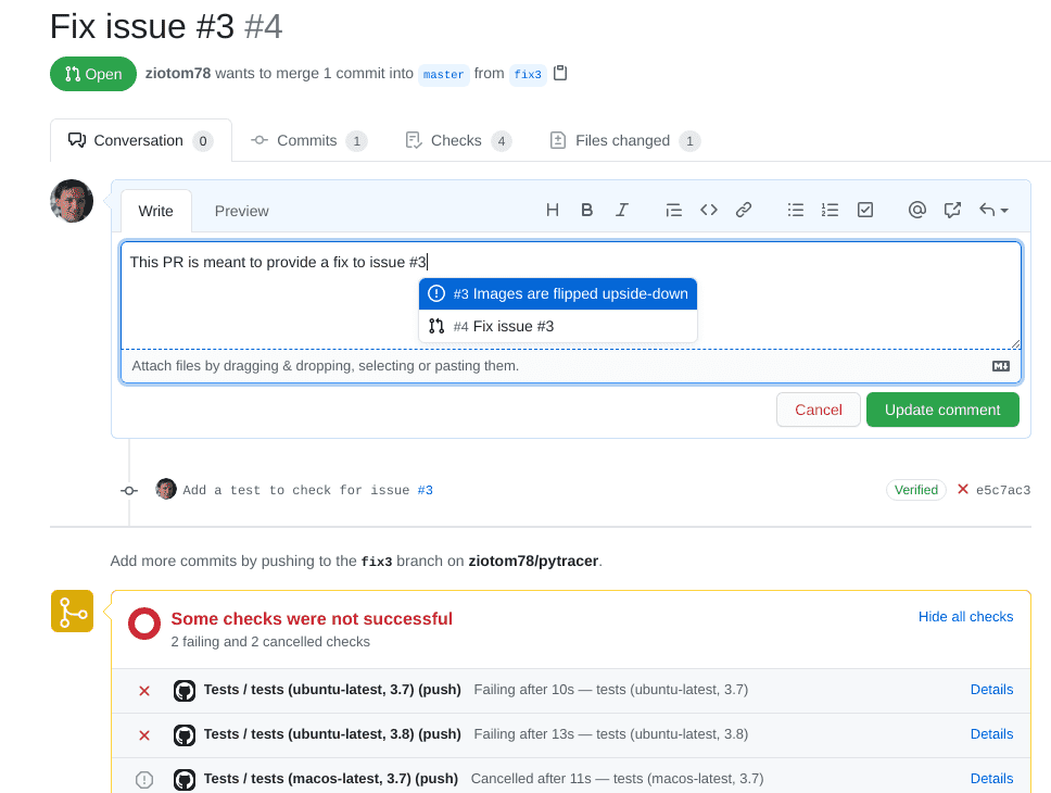
Opening an Issue
Creating a New Test
The test we had written for
ImageTracerwas not exhaustive……but it was already quite complex, because it verified two distinct things:
The correctness of the handling of
u_pixelandv_pixelThe fact that
ImageTracer.fire_all_rayswas able to “visit” all the pixels of the image.
It is not advisable to add material to this test, otherwise if it fails in the future it would be less immediate to understand where the problem lies.
Work to Do
What we will do now is divide the test into three sub-tests:
- The two existing checks, which however must be divided into two distinct tests;
- A new test that fails due to the bug we highlighted.
In implementing this test in Python, I used a feature of the testing framework (
unittest) that probably also exists in your frameworks. (If you cannot find it, look for alternative terms like “fixtures”, “before clauses”, …)
Inelegant Repetitions
def test_uv_sub_mapping():
    # Create the objects to test
    image = HdrImage(width=4, height=2)
    camera = PerspectiveCamera(aspect_ratio=2)
    tracer = ImageTracer(image=image, camera=camera)

    ray1 = tracer.fire_ray(0, 0, u_pixel=2.5, v_pixel=1.5)
    ray2 = tracer.fire_ray(2, 1, u_pixel=0.5, v_pixel=0.5)
    assert ray1.is_close(ray2)

def test_image_coverage():
    # Create the objects to test (same as above)
    image = HdrImage(width=4, height=2)
    camera = PerspectiveCamera(aspect_ratio=2)
    tracer = ImageTracer(image=image, camera=camera)

    tracer.fire_all_rays(lambda ray: Color(1.0, 2.0, 3.0))
    for row in range(image.height):
        for col in range(image.width):
            assert image.get_pixel(col, row) == Color(1.0, 2.0, 3.0)
Set-up e tear-down
The repetition arises because we must re-initialize the
image,camera, andtracerobjects in every test.Test frameworks (not all 🙁) usually provide the ability to invoke set-up procedures to create the objects on which the tests are then executed.
(Similarly, these frameworks also implement the ability to invoke tear-down procedures at the end of the tests, for example to delete temporary files created during the tests themselves).
class TestImageTracer(unittest.TestCase):
    # This is invoked automatically before *every* test
    def setUp(self):
        self.image = HdrImage(width=4, height=2)
        self.camera = PerspectiveCamera(aspect_ratio=2)
        self.tracer = ImageTracer(image=self.image, camera=self.camera)

    def test_orientation(self):
        # Fire a ray against top-left corner of the screen
        top_left_ray = self.tracer.fire_ray(0, 0, u_pixel=0.0, v_pixel=0.0)
        assert Point(0.0, 2.0, 1.0).is_close(top_left_ray.at(1.0))

        # Fire a ray against bottom-right corner of the screen
        bottom_right_ray = self.tracer.fire_ray(3, 1, u_pixel=1.0, v_pixel=1.0)
        assert Point(0.0, -2.0, -1.0).is_close(bottom_right_ray.at(1.0))

    def test_uv_sub_mapping(self):
        ray1 = self.tracer.fire_ray(0, 0, u_pixel=2.5, v_pixel=1.5)
        ray2 = self.tracer.fire_ray(2, 1, u_pixel=0.5, v_pixel=0.5)
        assert ray1.is_close(ray2)

    def test_image_coverage(self):
        self.tracer.fire_all_rays(lambda ray: Color(1.0, 2.0, 3.0))
        for row in range(self.image.height):
            for col in range(self.image.width):
                assert self.image.get_pixel(col, row) == Color(1.0, 2.0, 3.0)
Creating a PR
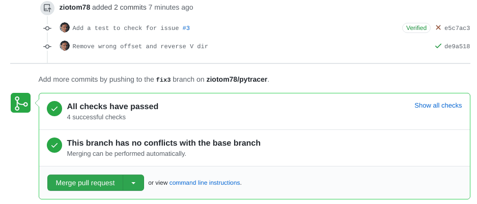
Correcting a bug
These are the correct instructions to use in
ImageTracer.fire_ray:If we commit this, the test will now pass:
![]()
Closing the issue
At this point the bug is fixed, and we can proceed to close the issue.
It is very important, however, to first take a general look at the PR to verify that it is clearly legible. In particular, select the Files changed tab and read it critically:
Are the files being modified the ones I expect, or are there other changes that I was working on when the bug was discovered? (See this example).
Will those who see these changes be able to understand them without reading the entire codebase?
Avoid unnecessary changes (drive-by commits) that are unrelated to the bug.
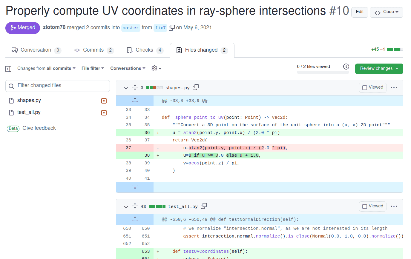
Example taken from a PR for pytracer
Closing a bug
Bug Tracking
GitHub tracks a repository’s bugs on a dedicated page: you can see which bugs are open and which have been closed.
But, as with commits, a list of bugs is quite poor, and doesn’t tell a “story.”
Let’s see now the purpose of the CHANGELOG.md file, which is a type of documentation.
CHANGELOG
All public repositories should have a
CHANGELOG/NEWS/HISTORY/… file, which lists bugs fixes and new features, organized by version number.See for example the
HISTORY.mdfile of the Julia compiler
CHANGELOG
In a
CHANGELOGfile you should indicate all the corrections and modifications made to the code.Keep it concise: one or two lines per change are sufficient, provided you include a link to the corresponding issue or pull request
It should be written in reverse chronological order: the most recent changes are at the top. This makes it easier for the reader to see what’s new in the latest version (which is likely the one they want to download).
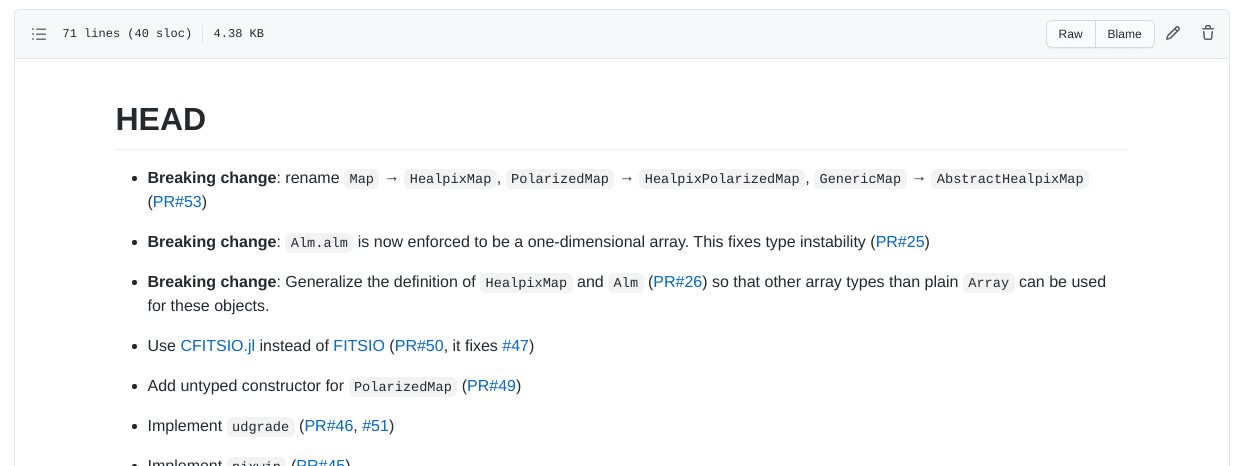
It is usually divided into one section for each version of the code. The first section is called
HEADor[Unreleased], and contains the corrections and modifications that will end up in the next future version of the code.
CHANGELOG of Healpix.jl
CHANGELOG of pytracer
In the pytracer repository there is a
CHANGELOG.mdfile, written in Markdown, which you can use as inspiration. In particular, “our” bug appears like this:Remember from now on that the last commit in a PR should always be the update of
CHANGELOG.md!
Our “black triangle”!

Geometry
Shapes
We need to implement shapes in our code.
For today, implementing a
Spheretype is sufficient; you may also add aPlaneif you wish (it’s very quick to implement).Create an abstract type
Shape, which implements the (abstract) methodray_intersection. This accepts aRayparameter and returns aHitRecordtype. If your language supports it, you can make the return type nullable (intersection exists/doesn’t exist).
Shape in Python
HitRecord
To return information about an intersection, it’s good practice to use a dedicated type:
HitRecord.This type should contain the following information:
world_point: 3D point where the intersection occurred (Point);normal: surface normal at the intersection (Normal);surface_point: (u, v) coordinates of the intersection (new typeVec2d);t: ray parameter associated with the intersection;ray: the light ray that caused the intersection
For testing, it’s helpful if it implements an
is_close/are_closemethod.
Sphere in Python
We found that the intersection is determined by the discriminant
\frac\Delta4 = \left(\vec O \cdot \vec d\right)^2 - \left\|\vec d\right\|^2\cdot \left(\left\|\vec O\right\|^2 - 1\right).
If \Delta > 0, the two intersections are
t = \begin{cases} t_1 &= \frac{-\vec O \cdot d - \sqrt{\Delta / 4}}{\left\|\vec d\right\|^2},\\ t_2 &= \frac{-\vec O \cdot d + \sqrt{\Delta / 4}}{\left\|\vec d\right\|^2}. \end{cases}
Numerical robustness
If the ray starts from a very far point and the sphere is small, then the two values t_1 and t_2 might be very close.
In this case, \Delta / 4 might become so small that it could suffer from catastrophic cancellation: in a quadratic equation a t^2 + b t + c = 0, this happens when b^2 \approx 4 a c but both terms are large.
We can rewrite it using Lagrange’s identity in 3D, which states that for two 3D vectors \vec a and \vec b, the following relation holds:
\left\| \vec a \right\|^2 \left\| \vec b \right\|^2 - (\vec a \cdot \vec b)^2 = \left\| \vec a \times \vec b \right\|^2.
Numerical robustness
Rewriting \Delta / 4, we get
\frac\Delta4 = \left(\vec O \cdot \vec d\right)^2 - \left\|\vec d\right\|^2\cdot \left(\left\|\vec O\right\|^2 - 1\right) = \left\|\vec d\right\|^2 - \left\|\vec d \times \vec O\right\|^2
Now the only way catastrophic cancellation can occur is when \left\|\vec d\right\|^2 \approx \left\|\vec O\right\|^2 and \vec d \perp \vec O, i.e., when we are close to the sphere’s surface and are looking along a tangential direction. In this case, t_{1/2} is small and will be rejected by our code.
Sphere in Python
You must inverse transform the ray before calculating the intersection:
Once you have calculated
t1andt2, you must determine which of the two intersections is closest to the ray origin:
Normals and UV Coordinates
You must implement the calculation of the normal at the intersection point; in the pytracer code this is done inside
_sphere_normal:You also need code that calculates the intersection point on the sphere’s surface, in (u, v) coordinates, for which a new
Vec2dtype is useful:
Creating HitRecord
Tests for Sphere (1/2)
- The ray with O = (0, 0, 2) and \vec d = -\hat e_z must intersect the unit sphere at point P = (0, 0, 1) with normal \hat n = \hat e_z.
- The ray with O = (3, 0, 0) and \vec d = -\hat e_x must intersect the unit sphere at point P = (1, 0, 0) with normal \hat n = \hat e_x.
- The ray with O = (0, 0, 0) and \vec d = \hat e_x must intersect the unit sphere at P = (1, 0, 0) with normal \hat n = -\hat e_x (the ray is inside the sphere).
In all these cases, also verify the (u, v) coordinates and the value of t.
Tests for Sphere (2/2)
- Apply a translation \vec t = (10, 0, 0) to the sphere and intersect it with the ray with O = (10, 0, 2) and \vec d = -\hat e_z.
- Intersect the same translated sphere with the ray with O = (13, 0, 0) and \vec d = -\hat e_x. The intersection should be P = (11, 0, 0) with normal \hat n = \hat e_x.
- Verify that the ray used in the first test no longer hits the sphere
after it has been translated:
- Ray with O = (0, 0, 2) and \vec d = -\hat e_z;
- Ray with O = (-10, 0, 0) and \vec d = -\hat e_z;
In all these cases, also verify the (u, v) coordinates and the value of t.
The World Type
- A scene is composed of many shapes.
- We need a type to contain this list of shapes: the
Worldtype. - It must maintain a list of
Shapeobjects: take care to declare this list correctly, as some languages may require special care for lists of abstract objects (e.g., a trait object vector in Rust). - It must implement a
ray_intersectionmethod that iterates over the shapes, searches for intersections, and returns the one closest to the ray origin.
World in Python
class World:
    def __init__(self):
        self.shapes = []

    def add(self, shape: Shape):
        self.shapes.append(shape)

    def ray_intersection(self, ray: Ray) -> Optional[HitRecord]:
        closest = None  # "closest" should be a nullable type!
        for shape in self.shapes:
            intersection = shape.ray_intersection(ray)

            if not intersection:
                continue

            if (not closest) or (intersection.t < closest.t):
                closest = intersection

        return closest
Our demo
The asymmetry in the arrangement of the spheres helps in detecting errors in the image row/column ordering.
The Scene
- Position the spheres at the vertices of the cube with edges (\pm 0.5, \pm 0.5, \pm 0.5), plus two spheres at (0, 0, -0.5) and (0, 0.5, 0).
- Each sphere must have a radius of 1/10.
- The observer should be moved by -\hat e_x, placing them at (-2, 0, 0) with the screen center at (-1, 0, 0).
- Choose whether to use
OrthogonalCameraorPerspectiveCamera.
The main
- Our
mainhas so far been able to convert a PFM image into another format (PNG, JPEG, WebP, etc.) - We must now change the program’s interface so that it allows the use
of two modes:
- Conversion from PFM to other formats (the old mode);
- A new
demomode, where it generates the image described above.
Example in Python
In Python, I used the Click library, which allows building command-line interfaces (CLIs) that support subcommands (also known as actions or verbs).
After the executable name, a command should be provided, optionally followed by parameters:
./main.py pfm2png input.pfm output.png
./main.py demo --width=480 --height=480
./main.py --help
...
Possible Interfaces
Actions exactly like Click (if your library supports them);
Two separate executables:
demoandpfm2pngInteractive terminal input (not recommended for automation):
Et cetera…
demo Command
- Initialize a
Worldobject with the 10 spheres in the indicated positions; - Create an
OrthogonalCameraorPerspectiveCameraobject (pytracer allows the user to choose); - (Optional) You can try rotating the observer to obtain more interesting angles (see below);
- Create an
ImageTracerobject; - Perform image tracing, using an “on/off” criterion (see next slide);
- Save the PFM image;
- (Optional) Immediately convert the image to PNG using default values for tone-mapping.
On-Off Tracing
An on/off ray-tracer checks if the ray has hit a surface, and if so, colors the pixel with an arbitrary color (white), otherwise it colors it with the background color (black).
In our case, it is sufficient to invoke
fire_all_raysby passing a one-line function as an argument:
Animations
In
demomode, the Python code allows modifying the orientation of the observer relative to the axes using the--angle-degflag.This can be used to generate animations through simple Bash scripts:
for angle in $(seq 0 359); do
    # Angle with three digits, e.g. angle="1" → angleNNN="001"
    angleNNN=$(printf "%03d" $angle)
    ./main.py demo --width=640 --height=480 --angle-deg $angle --output=img$angleNNN.png
done

# -r 25: Number of frames per second
ffmpeg -r 25 -f image2 -s 640x480 -i img%03d.png \
    -vcodec libx264 -pix_fmt yuv420p \
    spheres-perspective.mp4
Perspective Projection
Orthogonal Projection
What to do today
What to do today
- Fix the bug from last time by opening an issue;
- Create a
CHANGELOG.mdfile; - Create and switch to a new
demobranch; - Create the
Shape,Sphere,World,Vec2d,HitRecordtypes; - Implement the
democommand using your preferred method (you can look for a library to interpret the command line); - Open a PR and update the
CHANGELOG.mdfile.
Hints for C++
Hints for C++
To replicate the command-line interface provided by Pytracer, check the libraries in Awesome C++ [CLI].
To implement the
Worldtype, usemake_sharedandshared_ptr: in this way, you avoid callingnewanddeleteto create/destroy objects derived fromShape. (Bothnewanddeleteshould be avoided whenever possible: they are rarely needed in real-world code!)
Example with shared_ptr
#include <iostream>
#include <memory>
#include <vector>

using namespace std;

struct Shape { virtual ~Shape() = default; };
struct Sphere : public Shape {};
struct Plane : public Shape {};

int main() {
  // This would work even if "Shape" were an abstract type
  std::vector<std::shared_ptr<Shape>> list_of_shapes;

  // This calls "new" automatically, and it will call "delete" at the end
  list_of_shapes.push_back(make_shared<Sphere>());
  list_of_shapes.push_back(make_shared<Sphere>());
  list_of_shapes.push_back(make_shared<Plane>());
}
Hints for C#
Hints for C#
Today there should not be significant issues.
Given that
Shapemust contain theTransformationinstance, it’s probably better to use anabstract classrather than aninterface, as the latter cannot have data members.If you want to implement a good command-line interface, have a look at the repository Awesome .NET [CLI].
Hints for Julia
Hints for Julia
Don’t worry too much about the command-line interface: Julia programs are not meant to be executed from the command line. You could just provide a script named
demo.jlalongside another script calledpfm2png.jl.Define an
abstract typeforShapeand then deriveSphere,Plane, etc..In this lesson, you will likely see how elegant can be mathematical code in Julia!